- Details
- Geschrieben von Ralf Kästner
- Hauptkategorie: Network
- Veröffentlicht: 03. Juni 2009
- Zugriffe: 51033
Information about the interface-hardware and how it works in a Z80-System.
Evolution stages
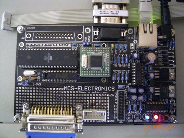
I read the first information about the hardware TCP/IP-stacks of "WIZnet" in 2003. But I could not find sufficiently information on how to use these chips. It took until autumn 2006, when I discovered the "Easy TCP" project of MCS Electronics from the Netherlands. They offered an experimental MCU-board for an Atmel 8051/52 or ATmega with the first WIZnet-stack W3100A. An assembler library for AVR-BASCOM was included with the board, to program the stack.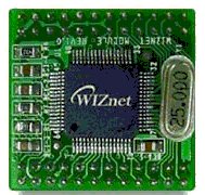
That was exactly what I had waited for. I knew BASCOM and I had already programmed the Atmel ATmega's in assembler. I ordered the kit and tried it out. I had to solve some problems with the BASCOM program examples, but the stack worked immediately! Subsequently, the assembler library and the datasheet of the W3100A were analyzed, to learn how the stack must be programmed.
Because of another project, the work on TCP/IP paused until March 2007. Then, I undertook the first attempts with the KC85 system.
The MCU-board and the Z80 system were connected. Then, some experimental assembler software was programmed for the ATmega, which executed commands from the KC85. Finally, I made another program for the KC85 system, to get the TCP/IP-stack initialized from there.
The first big step was done one week before the annual meeting of the german KC-Club. The KC was able to write an IP-address and subnetmask in the registers of the W3100A and to initialize it. Then, a PING from another computer was answered by the KC85.
So far, so good ? No, there were some concerns and doubts with the W3100A. It was introduced in 2002, WIZnet was not idle meanwhile and had further developments on the market with W3150/W3150A (2005) and W3150A+ (2006).
I had noticed it negatively already in 2006 with the study of the W3100A datasheet and the assembler-routines from the BASCOM library, that driver programming would not be trivial and somewhat awkward too. After I had compared this with the W3150A+, it was quickly clear, these disadvantages were no more present in the second generation of the TCP/IP stack and that actually, one could continue the project, but only with the current chips.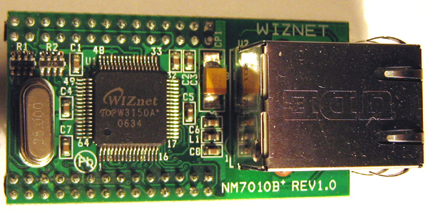 Therefore, in May 2007, I tested, whether the more current TCP/IP stack W3150A+ could be also used with my experimental MCU-board. I found with pleasure that only some small alterations needed to be performed on the original MCU board. Then, everything should work electrically, as previously.
I ordered the second network module NM7010B+ afterwards, with a W3150A+, and rebuilt the circuit board accordingly. The program for the KC85 was altered after this and the first test executed with the W3150A+. It worked straight away, exactly like the W3100A.
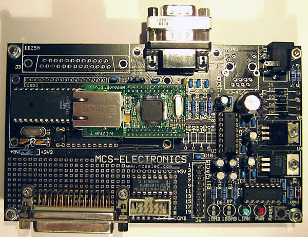
The second pause in the project was from May to September 2007, because of other work. The main development phase started after the summer in September 2007. KCNet-II was the platform for the development of the first final Firmware-Version 1.1 for the ATmega MCU, which was ready in November 2007. Then, the first Z80 driver software was written until January 2008.
In the following period, the socket API was created. Together with the first three network programs, the project was demonstrated at the annual KC85 meeting in March 2008. A long optimization phase followed then, with many software improvements, new KC85 interface drivers and Firmware-Version 1.2 for the ATmega MCU.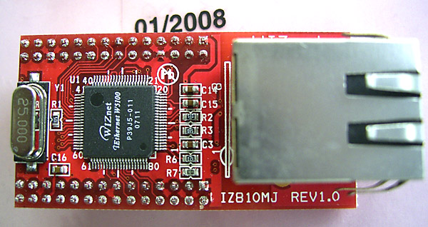
In June 2008, a last test was performed with the most recent and cheapest TCP/IP-stack W5100. It integrates the Ethernet controller inchip now, and the third ordered network module WIZ810MJ costs around 20 EUR only.
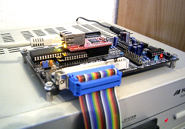
This module has some very little differences in the output of a stable /LINK signal, but the TCP/IP core is fully compatible with the predecessor W3150A+. I simply replaced the old module with the new one and everything ran like before. So the third variation of the KCNet came into operation and this is the last and recommended version for other hardware applications, please look at "Network Modules" for more information also.
KCNet-III was also the basis for the development of our KC85 Network & USB Module M052. This was done from summer 2008 up to January 2009. The following picture shows one prototype with the professional board.
KC85 Module M052 with KCNet-III (left half of the board)
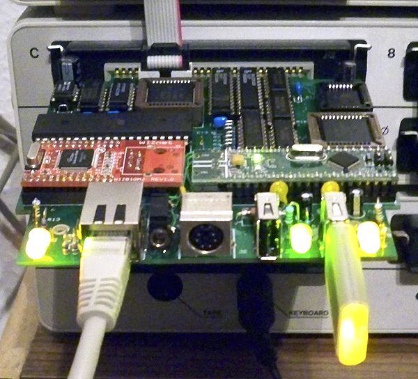
Finally all tests of the M052 passed successfully, and the new KC85 Module was presented at the annual meeting of the KC-Club in 2009.
With the help of this module, the KC85 system is technically capable to use the services of TCP/IP Ethernet-networks in the CP/M operation mode, as well as in the CAOS operation mode.
In June 2009, the first production run of more than 60 M052 Module-Kit's for KC85 users was started ...
Hardware TCP/IP-Stack
From the inventor of the W5100: "Unique Network Solution, It couldn't be Simpler, Stabler & Smarter! Fully Hardwired TCP/IP. Success belongs to you". WIZnet praises their so called "ioffload System" with the fact that it strongly unburdens an embedded MCU system. The system load through the TCP/IP-network decreases from 72% to 37% if, instead of a software, a hardware stack is used.
Summary of WIZnet hardware TCP/IP stacks
| Stack | Year | MCU-Bus | TCP/IP Core | Sockets / Tx- / Rx-Memory | Note |
| W3100A | 2002 | 8-bit | I | 4 / 8 kB / 8 kB | |
| W3150 / W3150A | 2005 | 8-bit | II | 4 / 8 kB / 8 kB | |
| W3150A+ | 2006 | 8-bit | II (modified) | 4 / 8 kB / 8 kB | |
| W5100 | 2007 | 8-bit | II (modified) | 4 / 8 kB / 8 kB | inchip Ethernet-Controller |
| W5300 | 2008 | 8/16-bit | II (modified) | 8 / 64 kB / 64 kB | inchip Ethernet-Controller and memory manager |
All WIZnet stacks replace the layers 1 to 3 of a common software TCP/IP stack with hardwired logic.
The W5100 used, is the last 8-bit-only stack with the following benefits:
- Performance:
- Line-Speed Data Transmission by Hardwired Logic
- up to 25 Mbps throughput at application layer
- Easy Implementation:
- Easy & Simple Control like Memory
- Save Development Time
- Cost Effectiveness:
- TCP/IP Implementation without OS
- MAC & PHY Embedded
WIZnet mentions the following key features:
- Support Hardwired TCP/IP Protocols: TCP, UDP, IP, ICMP, IGMP,IPv4 ARP, PPPoE, Ethernet
- 10BaseT/100BaseTX Ethernet PHY embedded
- Support Auto Negotiation (Full-duplex and Half-duplex)
- Support Auto MDI/MDIX (crossover detection)
- Support ADSL connection (with support PPPoE Protocol with PAP/CHAP Authentification mode)
- Support 4 independent sockets simultaneously
- No support of IP-Fragmentation
- Internal 16 kBytes Memory for Tx/Rx Buffers
- 0,18 µm CMOS technoloy
- 3,3 V operation with 5 V I/O signal tolerance
- small 80 Pin LQFP Package
- Lead-Free Package
- Support 3 different interfaces, direct memory access, indirect memory access and SPI Mode 0 and 3
- Multi-function LED outputs (Tx, Rx, Full/Half duplex, Collision, Link, Speed)
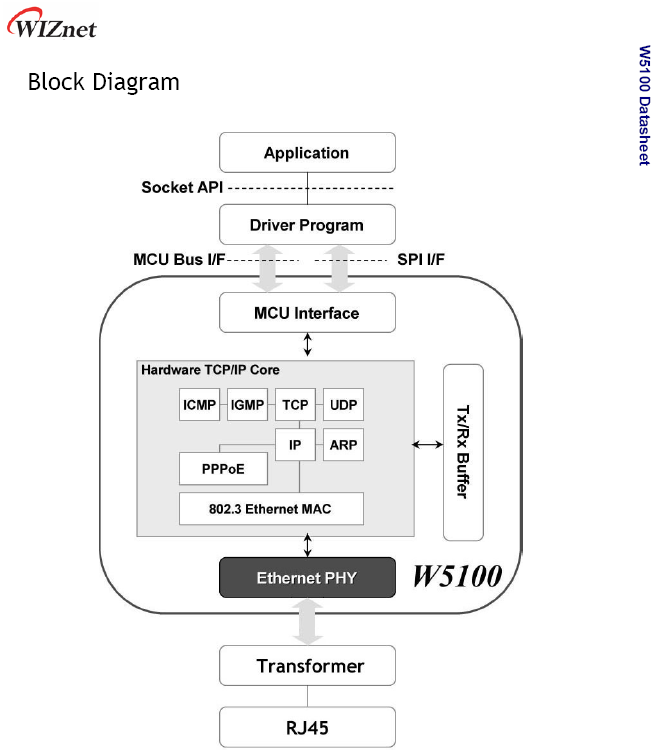
The KC85 or a CP/M computer were not listed as target devices, but this piece of hardware met my requirements for the use as a TCP/IP-controller in an Ethernet network for my system almost perfectly. The next picture shows once again the familiar block diagram. This was the principle plan to integrate the TCP/IP stack in my system. All "green and yellow" protocols of a TCP/IP implementation run in the W5100. The only real obstacle was the physical connection with my Z80 system, see next section of this article.
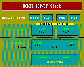
All WIZnet stacks are like memory in a system. The control-interface is a set of hardware addresses, which are established by the hardware designer and then covered from the chip. The TCP/IP core-II is almost always the same in all chips, there are slight differences in the meaning of cells or bits of cells. WIZnet had to remove errors from the W3150 and modified some details in the successor W3150A. All alterations led to the modified core-II of the W3150A+ or W5100.
Because the W5100 is hardwired logic and not a device-interface of a software-controlled other system, there isn't any command set as usual. The W5100 is composed of 4 main memory areas which have defined tasks:
| Common Register | - stack operation mode - network configuration - interrupt behavior - TCP timing - socket memory configuration |
Base address + 0000H, 48 Bytes |
| Socket Register |
- socket operation mode |
Base address + 0400H, 4*256 Bytes per socket |
| Tx Memory | - Tx socket-memory Buffer (read/write) | Base address + 4000H, 8192 Bytes |
| Rx Memory | - Rx socket-memory Buffer (read only) | Base address + 6000H, 8192 Bytes |
Chapter 2 of the W5100 datasheet contains an example memory map. These addresses are valid if the base of the stack is 0000H in a real system:
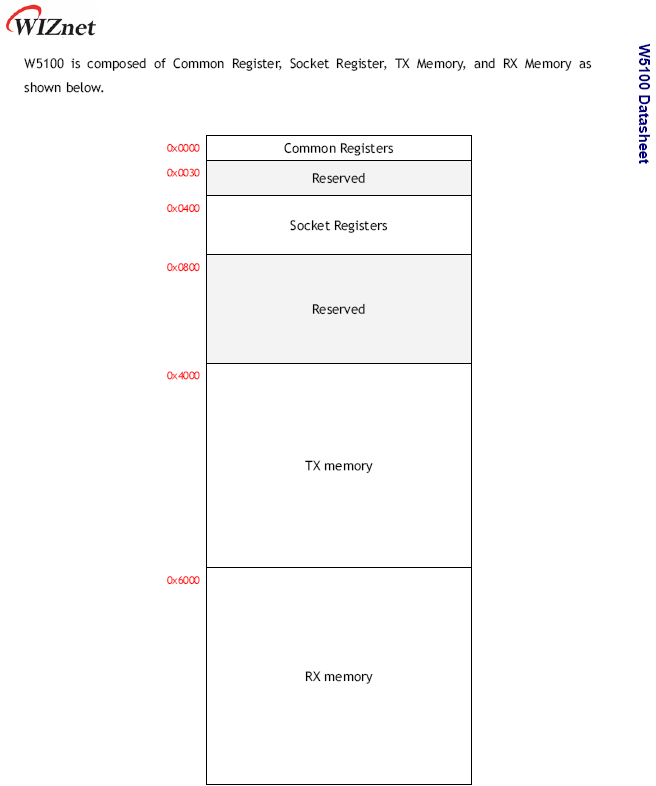
Chapter 3 lists all accessible registers of the W5100 with address and name relative to address 0. In chapter 4, the functional description of all registers and their bits is carried out in detail : this is the most important chapter for the programmer of such a TCP/IP-stack. There are many explanations and state diagrams, which help to understand all functions.
Chapter 5 contains pseudocode for fundamental TCP/IP applications on the various layers, which such a stack has to do:
- TCP Server Mode
- TCP Client Mode
- UDP Mode
- IP Raw Mode
- Ethernet Raw Mode (MAC)
All of these pseudo-applications worked like expected. The Z80 code implementations are parts of the interface testprogram CPMNET.COM, and allow playing with a TCP/IP network without a higher protocol on the TCP-, UDP-, IP- and MAC-layer of the stack.
The not mentioned chapters of the datasheet describe all pins of the chip, possible hardware applications, electrical-, solder- and package-specifications. Since a ready-made network module is used, that is not of interest here.
Functional Idea
The target platforms for a WIZnet stack are the various MCU families, like PIC's, AVR's or ARM's. A hardware stack does the work of the lower layers and the controller can do its application without restrictions. Hardware-based TCP/IP-stacks consume less memory and do not need high system-performance for a liquid work of the entire system. The conditions in small 8-bit controller systems are the same as in my Z80-based system : a maximum of 64 kB memory and low clock rates.
WIZnet made the following test in order to demonstrate the advantages and capabilities of the W5100, a W3150A+ gives the same performace. A program is running in the MCU, which echoes all data sent from a PC program, which calculates the bitrate. The table lists the Data-Throughput in Mbps of the chip on the application layer:
| Testing MCU : | Atmega 128L-8AU External 8 MHz Crystal |
| Compiler : | WIZnet "C"-Driver compiled with WinAVR AVR GCC 3.4.6 |
| Testing Tool : | WIZnet "AX1.EXE" |
| Testing method : | Loopback test with the files (Direct 7,8 MB / Indirect 2,56 MB / SPI 948 kB) |
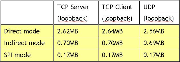
The controller of my experimental board is an ATmega 162 with 8 MHz, so the measured values should be similar in my case. This means for the project that the chip is very fast in the network! The Z80 system itself is probably the slowest link in the chain of transmission, as I already had suspected.
How does it works? The W5100 is in the address space of the controller, and can be addressed from 8000H - FFFFH. All given addresses of the memory map or datasheet has to be added an offset of 8000H. This must be done because of hardware requirements. Now could a controller-application write or read the W5100, and thus use the TCP/IP stack like the driver and example programs provided from WIZnet do.
See the following picture:
But that was not my goal : I wanted to program the stack by myself with an application running in the Z80 system, a native solution without programming restrictions! The link between the W5100 and the Z80 must look like the chip would be directly in the Z80 address space. Then, a network application can run in the Z80 system and the W5100 executes all network protocols of the TCP/IP-stack from the transport layer downwards.
The first obstacle was the electrical problem. A W5100 has a standard MCU bus interface and my system has a standard Z80 bus. Both are not compatible and cannot be connected directly. But the ATmega 162 has the necessary MCU bus interface and there was one big advantage : it was tested with the connected W5100 and it functioned. Never touch a running system! So this problem was solved by the experimental board itself.
Since the stack is like memory, all programming is done through read and write commands from the controller. When writing an address, you can trigger actions or put data on the stack. When reading an address, you can get status information or read back data from the stack.
A Z80 does this reading or writing of addresses exactly in the same way in its own address space and the 8-Bit controller ATmega 162 is fully compatible with the Z80 in reading and writing. It uses 16 bits for an address, 8 bits for a data byte and is working with Little Endianess in the organization of data in memory, so that is the ideal extended workbench for the Z80 system :-).
This consideration turned into the basis idea of the KCNet interface. All application and driver software can be done in the Z80 system, which works with the virtual addresses of the controller-system. Directly before the physical read or write commands are executed, the address and/or data have to be transfered to the controller-system unchanged! Then, the ATmega reads and writes the chip addresses of the W5100 in the MCU system and gives data back, if required.
What are the advantages of this approach:
- I didn't need other hardware, because the tested controller board met my needs :-)
- the Z80 software does the logical programming of the TCP/IP-stack, not the controller : I have my native Z80 solution
- I do not need real memory space of the Z80 system for a possibly direct connected WIZnet-stack (that would require much more additional hardware!)
- address- or data-structures of the Z80 system need no conversion, they can be transfered 1:1 and used from the controller directly, this ensures a high speed in the execution of commands
- every existing programming environment and language of the Z80 system is usable
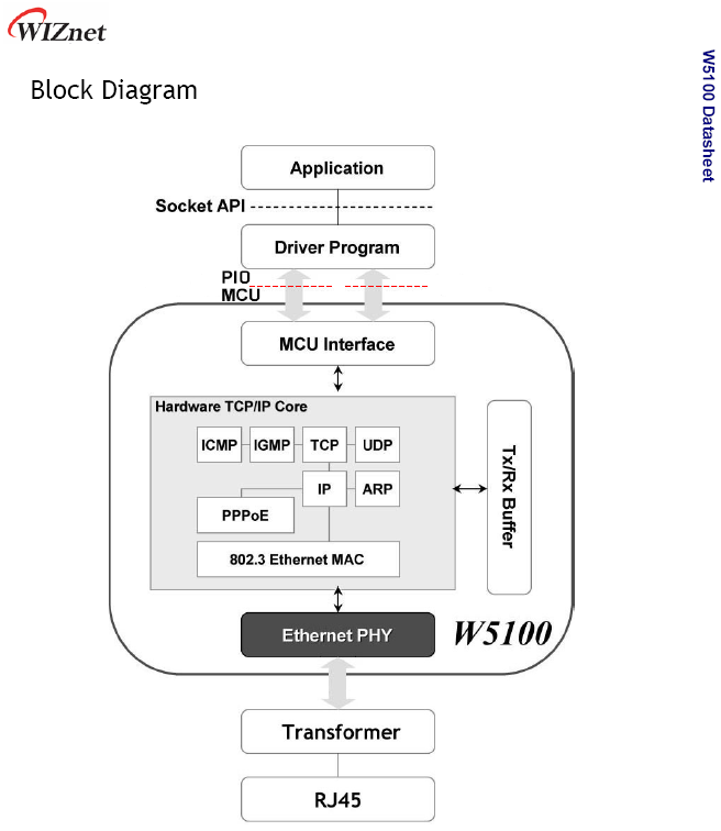
The KCNet-Interface changes the WIZnet model.
"Application", "Socket API" and "Driver Program" run in the Z80 system. The KCNet hard- and software handles the transfer and execution of write- or read-commands. This is done at the lowest possible level, between the "Driver Program" and "MCU Interface".
The red line in the following picture indicates the location of the chain, where the transfer is carried out:
Since the ATmega reads and writes the chip addresses of the W5100, I had to connect the Z80 system with the MCU system. This connection had to be as fast as possible, to maintain much of the high W5100 data-throughput! In order to be universal and absolutely compatible with each Z80-System, only a standard-circuit of the Z80 family was acceptable for the link to the ATmega.
Because no peripheral interfaces with Mbps data-rates exist for my old system, the Z80-PIO came into the game at this point. This decision was taken very quickly, my Z80 system with 1,77 MHz clock rate is the bottleneck of the entire transfer-chain. In order to gain a certain usability of the network for the user, at least 10 kByte/s transaction rate was the aim. A Z80-SIO is not possible here, only with a fast parallel protocol were rates greater than 10 kByte/s feasible.
Now, the interface was complete with the PIO-ATmega connection. They communicate bidirectionally. The Z80-PIO is used in Mode 2, and the ATmega software emulates the PIO hardware-handshake protocol.
The next picture shows the lowest level of the KCNet hard- and software. All programs at the Z80 side use the Low-Level Interface-Driver KCN-ZPIO.INC for the communication. The ATmega software on the other side waits for commands, in order to read or write the physical addresses of the W5100:
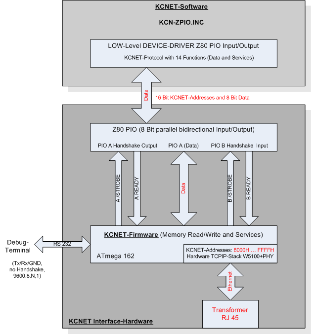
The "KCNet-Protocol" defines the permitted communication commands and their syntax. It ensures a smooth interplay between the two processor systems.
The software, which runs in the controller, is typically called firmware. Its main task is to read and write commands from the Z80 system to the W5100. In addition, it takes over further service functions for the Z80 hostsystem and administers the Ethernet MAC-address of the interface.
Moreover, this firmware includes a debug-interface for a terminal program. This enables the diagnosis of the KCNet hard- and software with or without a Z80 system during the commissioning of a new interface. The replica of the interface is so much easier, and a simple task for experienced users.
The KCNet interface fulfills my primary goals. The KC85 system has a free programmable TCP/IP stack, which is universal in the context of the capabilities of the W5100 and my system is not burdened.
Because one PIO is required only, the necessary system resources become limited on 4 free contiguous I/O addresses of the Z80 system.
These 4 I/O addresses should probably always be free, even in exotic systems. Thus, nothing should speak against a nearly unlimited re-use of the interface hardware in Z80 systems.
Hardware
The following picture shows the main components of a KCNet interface. It is not a pure hardware solution, but a combination from hard- and software.
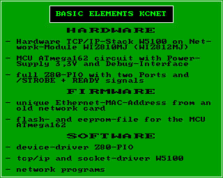
So far, implementations exist for our KC85 system and a card for K1520 bus systems, the standard bus of CP/M business computers in the former G.D.R.
A complete interface card for a Z80 system consists of a Z80-PIO with address bus decoder, data bus driver, control bus logic and the hardware of the KCNet-Interface.
Z80-System:
The M052- and K1520-implementations contain examples for Z80 bus connections. The "Zilog-Peripherals" board of "The N8VEM Home Brew Computer Project" is also a good starting point for the Z80 side of the hardware:
You can use a possibly existing PIO of your system too, then only the interface-hardware is necessary.
The whole network-software runs with a polling device-driver at this time. It could be beneficial later, if the PIO could operate via interrupt in the Z80 system.
KCNet-Interface:
The interface hardware needs a current of about 200 mA and is connected to the 5V power supply of the Z80-System. An additional voltage of 3,3V is required for the network-module (the KCNet and K1520 circuits contain examples).
Circuit diagrams are available from the following implementations:
| KCNet experimental board | - | development board of the KCNet project |
| Network & USB Module M052 | - | special solution for the kc85 hardware-module bus |
| K1520 experimental board | - | basis for a common K1520 bus card |
The circuit components are:
- WIZnet Plug-in network module with the hardware TCP/IP stack (W5100 or W3150A+)
- 3,3V power regulator
- MCU ATmega 162 with reset generator, quartz generator 8 MHz and an individualized copy of the Firmware (unique MAC address !)
- 74HCT573 address latch
- 74HCT00 or 74HCT04 with inverting buffers
- 74HCT08 with 2-input AND gates (only necessary with network module WIZ810MJ)
- driver/receiver MAX232 for a standard RS-232 communication interface of the Debug-Terminal
- ISP plug for firmware programming (optional)
All components are commercially available and easy to get at electronics retailers.
The network modules are available at selected dealers or distributors of WIZnet. They can be ordered in Germany at www.dacomwest.de or www.watterott.com, for example.
Network Modules:
There are different WIZnet modules. You need one with 8-bit MCU bus interface and the "modified TCP/IP stack-II", in order to use the KCNet circuit and the Z80 driver software. There are some minor differences between usable modules. The network module WIZ811MJ is not suitable!
| TCP/IP stack: | W3150A+ |
| Connector Type: | two 2 mm x 14 Connectors |
| Dimension: | 52 mm x 25 mm |
| Notes: | connect /L_LINK output JP2:12 direct with MCU Pin 15 |
| TCP/IP stack: | W5100 |
| Connector Type: | two 2 mm x 14 Connectors |
| Dimension: | 52 mm x 25 mm |
| Notes: | connect /LINK_LED JP2:12 / TX_LED JP2:8 / RX_LED JP2:10 like in KCNet circuit with MCU Pin 15 and SPI_EN JP2:9 to Ground |
| TCP/IP stack: | W5100 |
| Connector Type: | two 2,54 mm x 10 Connectors |
| Dimension: | 55,5 mm x 25 mm |
| Notes: | connect /LINKLED J2:19 direct with MCU Pin 15 and pay attention to the following cross reference list (n.c. means not connected) |
Cross-Reference List WIZ810MJ - WIZ812MJ:
| WIZ810MJ | WIZ812MJ | ||||
| Name | Pin | Name | Pin | Note | |
| - | - | MOSI | J1:1 | n.c. | |
| - | - | MISO | J1:2 | n.c. | |
| D1 | J2:15 | D1 | J1:3 | ||
| D0 | J2:16 | D0 | J1:4 | ||
| D3 | J2:17 | D3 | J1:5 | ||
| D2 | J2:18 | D2 | J1:6 | ||
| D5 | J2:19 | D5 | J1:7 | ||
| D4 | J2:20 | D4 | J1:8 | ||
| D7 | J2:21 | D7 | J1:9 | ||
| D6 | J2:22 | D6 | J1:10 | ||
| GND | J1:8,13,24 | GND | J1:11 | ||
| VCC (3,3V) | J1:1 | VCC (3,3V) | J1:12 | ||
| A8 | J1:15 | A8 | J1:13 | ||
| A9 | J1:14 | A9 | J1:14 | ||
| A10 | J1:11 | A10 | J1:15 | ||
| A11 | J1:12 | A11 | J1:16 | ||
| A12 | J1:9 | A12 | J1:17 | ||
| A13 | J1:10 | A13 | J1:18 | ||
| A14 | J1:7 | A14 | J1:19 | ||
| - | - | n.c. | J1:20 | n.c. | |
| VCC (3,3V) | J2:24 | VCC (3,3V) | J2:1 | ||
| /RESET | J2:2 | /RESET | J2:2 | ||
| - | - | SCLK | J2:3 | n.c. | |
| - | - | /SCS | J2:4 | n.c. | |
| /WR | J1:3 | /WR | J2:5 | ||
| /RD | J1:4 | /RD | J2:6 | ||
| /CS | J1:5 | /CS | J2:7 | ||
| /INT | J1:2 | /INT | J2:8 | ||
| - | - | LED_RX | J2:9 | n.c. | |
| - | - | LED_TX | J2:10 | n.c. | |
| A0 | J1:23 | A0 | J2:11 | ||
| A1 | J1:22 | A1 | J2:12 | ||
| A2 | J1:21 | A2 | J2:13 | ||
| A3 | J1:20 | A3 | J2:14 | ||
| A4 | J1:19 | A4 | J2:15 | ||
| A5 | J1:18 | A5 | J2:16 | ||
| A6 | J1:17 | A6 | J2:17 | ||
| A7 | J1:16 | A7 | J2:18 | ||
| - | - | /LINKLED | J2:19 | direct to ATmega162 Pin 15 | |
| GND | J2:1,4,7,13,14,23 | GND | J2:20 | ||
Reproduction:
The block diagram shows the model for a common CP/M 2.x system. All network programs should work on every system, because of the standard system CALL's. For now, the complete driver software for a KCNet interface is integrated in the application, not in the BIOS. The PIO I/O address of the system and exotic Terminal Codes can be adjusted in one config file for all programs before the translation.
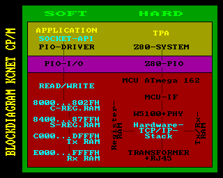
The building of an interface card for other systems shouldn't be a problem for advanced users. We can share our knowledge and assist you with our implementation experiences, but making one is your task. The implementation and test of such a card has to be done with the hardware of your systems : we can't do it for you!
Reproduction is relatively simple, because of the comparatively very low hardware cost. The use of a Z80 standard circuit and the built-in Debug-Terminal make it considerable safe. A problem should be found fast and easy in case of troubleshooting. A terminal program let you "look into" the MCU system via the debug-interface. This tool allows a test of the hardware TCP/IP stack independent from the Z80 system and monitoring the communication between MCU system and Z80 system in realtime.
The connection to an existing Ethernet home network is done with a simple network cable. All properties, including Ethernet crossover cable, are recognized automatically. The chip supports the PPPoE protocol via DSL modem too. This protocol is not supplied by the current software, but it could be programmed in principle.
There are some restrictions with the W5100. Only IPv4 is available, it can do 4 simultaneous connections to the network only, and it does not support IP fragmentation. But these restrictions have absolutely no significance in a private home network.
I was very happy in January 2008, when the KC had done its first connection to the PC in my network. The primary software applications are client programs. I don't have the intent to use my KC85 as an internet server :-) !
Firmware
The current version 1.2 of the controller firmware was made in July 2008. It has been in use one year already and passed many tests during this time. So, it should work without problems. The core functions of the KCNet-Protocol are very generic commands, this prevents updates.
An update would be necessary only if additional commands should be added or for expanding existing service functions. I have no future plans in this direction, because the effort is high, through the individualization with the unique MAC address for each firmware.
But it is software only, it can be updated in contrast to the interface-hardware.
Without this software, the interface is dumb hardware. The KCNet goes into operation with a programmed MCU only. You don't have to pay for the firmware, but fulfill some conditions, to get one. This is explained in paragraph "Delivery" later.
MCU-Programming:
You can burn the firmware by yourself, or get a preprogrammed MCU. I use an AVR ISP parallel port interface from the STK200, which is connected to a standard PC LPT port. The circuit for this simple ISP adapter can be found in the internet easily. If you place the optional ISP plug on the KCNet hardware, it can be used directly : this is handy for updates, too.
The settings of the controller fusebits are very important for the self-programmers. In each case, they must be changed! If you buy a new ATmega 162, they will not match the settings needed for the KCNet!
The following screenshot shows the correct settings of the fusebits for the widely used "Ponyprog 2000" burning program:
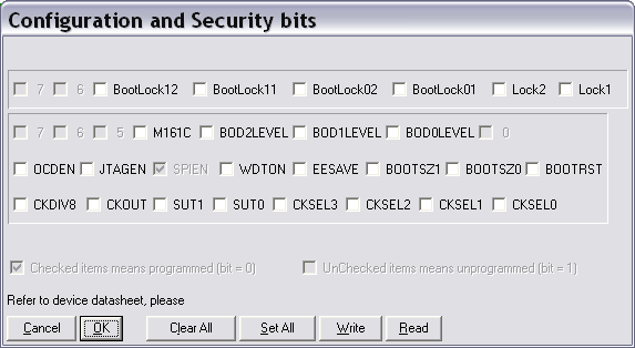
Two files have to be burned, one for the flash memory and one for the EEPROM memory of the controller (nnnn = serial number of your firmware):
nnnn.hex - firmware file for the flash memory (Intel hex file format)
nnnn.eep - firmware file for the EEPROM memory (Intel hex file format)
Don't forget to burn the EEPROM file! This is a common mistake, the KCNet interface does not work with an empty EEPROM! Use the verify-function of the burning software to ensure the correct contents of the chip after burning.
Check the help of your burning program, how intel-hex files have to be loaded. Some programs work properly only if the filetyp is "hex". Then, you have to rename the delivered EEPROM file before using it.
Step by step guide for "Ponyprog 2000":
- Command -> Security and Configuration Bits ...
- adjust all settings according to the picture above
- Button 'Write'
- File -> Open Program (FLASH) File ...
- select and open the "nnnn.hex" file
- File -> Open Data (EEPROM) File ...
- select *.eep filetyp with the drop-down selector
- select and open the "nnnn.eep" file
- Command -> Write Program (FLASH)
- Command -> Write Data (EEPROM)
- Command -> Verify All
- message "Verify successful" must be shown.
PIO-Handshake:
The firmware of the controller can be adjusted flexibly, in contrast to the hardware of a PIO, which is hard-connected to the clock rate of the Z80 system. A crucial point is the PIO hardware handshake for data input and output to the periphery, which can be viewed in the Zilog datasheet.
I didn't found exactly information about the minimal length of the strobe-pulse, so the following way was chosen. This length is adjusted in dependency of the PIO clock rate. The minimal length is always a little bit longer than 1 clock length of the PIO clock rate. So, the PIO should surely recognize the strobe-pulse of the controller. Then, the handshake is able to synchronize the different system clock rates during data transfers under all circumstances.
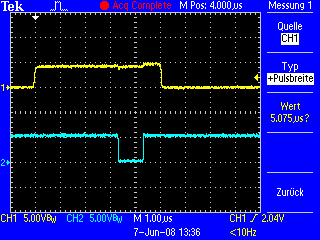
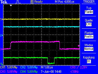
The diagrams show the handshake of the KC85 system for example. These pictures were recorded during the development and test of the second firmware version 1.2 in summer 2008.
|
|
|
| A Ready | ||
| A /Strobe | ||
|
|
|
| B Ready | ||
| B /Strobe | ||
Thus, the interface should work reliably with varying Z80 systems, and the pulse width of the /strobe signals are adjusted according to the clock rate of a system. On the other hand, the length of the pulses is only as long as necessary, and the speed of data transfer is always in the optimum range.
The right adjustment is made by the assembler, using the PIO clock frequency during the translation of the firmware. The pulse width is larger in slower, and smaller in faster Z80 systems. A range from 500 kHz up to 8 MHz PIO clock frequency is covered, which should fit for most of the systems.
These settings are readable over the Debug-Terminal. They can be viewed, just as the computer name of the Z80 system, for which the interface firmware has been translated.
Ethernet-MAC:
An unpleasant but very important thing is the MAC address for the network interface. It is required for the operation of the ARP protocol in the Ethernet layer and must differ with each participant in a network of the related segment (subnet). Therefore, it must be unique in order to connect to any networks, without disturbing the other (unknown) participants.
Unfortunately, the WIZnet chip comes without an built-in MAC address. Hence, the firmware in the controller must deal with this matter. Normally, manufacturers of network cards buy a pool of MAC addresses in whole packages for money! Because the KCNet is a hobby project, this was not an option for me.
I reject a distribution of the interface firmware without MAC address because this makes the commissioning of an interface more difficult. Furthermore, there is the danger that (foreign) networks are disturbed in their operating, if there are problems with the MAC address. Identical MAC addresses in a subnet can cause for a lot of confusion, and such problems are very difficult to diagnose.
For this reason, a valid MAC address has to be provided from interested users for each individual copy of the firmware and, thus, each interface.
The supplied MAC address is hard coded in the firmware, which manages it automatically during the operation of the interface. Since the MAC address cannot be changed subsequently, the firmware files must not be confused or double used : each interface needs its own version of the two files, so that the MAC addresses are different! The firmware executes a CRC test during the boot sequence, to guarantee the smooth running of the interface.
In order to get a MAC, use an old NIC (or new for 3,99 EUR) whose address can be adopted. Firstly, it ensures that the MAC address is valid and, secondly, that it is unique. The manufacturer of the real NIC is prohibited to sell network cards with the same MAC. After the acquisition of the MAC, the NIC should be trashed!
Sometimes, the MAC address is printed on the backside of the network card, or on a sticker. In the worst case, you have to install the card in a PC and get the MAC with a program or with the help of the operating system. Old ISA bus cards can be read out with the MS-DOS utilities from the NIC manufacturer websites.
A sequential serial number is awarded to each KCNet interface and is assigned, in conjunction with the MAC address, in an internal list. Before the release of a provided MAC address, a comparison with this list is carried out. An use can only be done, if this MAC address does not exist in the list!
Delivery:
Basically, there are two possibilities to get a copy of the firmware. A preprogrammed controller is delivered, which contains your individualized firmware. Or, an individualized copy of the firmware is delivered via E-mail, which must be burned into a controller itself.
Besides the important MAC address, I need the following information from an interested user for each copy of the firmware in separate form:
- Last and First Name
- E-mail address
- valid MAC address(es) for each copy of the interface firmware
- short name of the Z80 system (this name is displayed in the Debug-Terminal only, for example "KC85")
- clock frequency of the PIO (in most systems, identical with the system clock rate)
For each copy of the firmware there will be assigned a serial number. All important parameters of the individualized copy can and should be controlled in the delivered config file (plain text).
For each interface, a related pair of two files is required. Do never alter the content of files or swap files of different pairs. Do not use a pair of two files for more than one interface! Otherwise, in the worst case, the network can be brought to a standstill!
If an individual copy of the KCNet firmware with your data is delivered via E-mail, you will get a zipped folder with 3 files:
| config.inc | - | configuration file, which has been generated from your supplied data |
| "serial number".hex | - | firmware file for the MCU flash memory in Intel HEX formet |
| "serial number".eep | - | firmware file for the MCU EEPROM memory in Intel HEX format |
Debug-Terminal
After describing the interface hardware, we finally come to an important tool for builders. It is especially needed in case everything was made seemingly right in the Z80 system, but nothing happens when trying to test the interface with the Z80 software.
On the other hand, if the interface communicates immediately with the Z80 system, you can skip this section.
The terminal interface to the debugger has a second important function. The KCNet configuration data for the adaptation to the host system can be viewed safely only in this way.
The debugger works like a terminal. You need a keyboard, a screen and a serial interface. When a button is pressed, the key code is sent through the serial interface to the controller, the firmware in the controller processes the code and an answer is sent back via the same interface, which is displayed on the screen.
With the debugger, you obtain access to the MCU system, even without a functioning communication to the Z80. In this way, the complete hardware behind the Z80-PIO can be checked easy, in order to diagnose errors. If the ATmega works, you can test the memory interface and the function of the W5100 also. The real-time display of the PIO communication was a very useful feature in the beginning of the development. You are able to monitor the input- and output-streams to ensure that the commands of the KCNet protocol are processed correctly.
RS-232 cable:
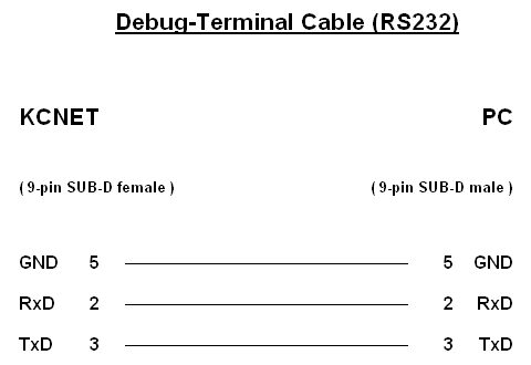
The common junction of the Tx- and Rx-lines is made behind the KCNet port, so that a commercially available 1:1 serial extension cable can be used, not a null modem cable! As you can see on the picture, the communication takes place without handshake, so that you don't have to deal with the remaining signals of the RS-232 interface.
That's all. After connecting, you can start the terminal software on the PC.
Terminal program:
The following description refers to the Windows program HyperTerminal. First, the communication parameters must be set correctly, after starting HyperTerminal:
interface:
- COM number
- Transmission speed 9600 Baud
- 8 Data bits
- 1 Stop bit
- no Parity
- no Handshake
ASCII-configuration:
- finish sent lines with line feed ON
- echo local character input ON
- attach line feed at received lines OFF
- receive input data in 7 Bit ASCII format OFF
- wrap too long lines in the terminal-window OFF
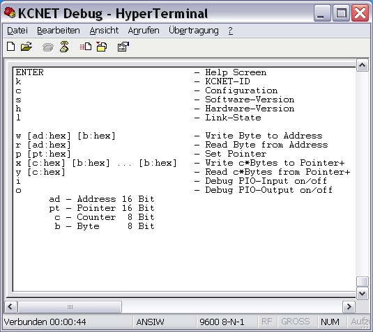
If not, check and verify once again the connection, the cable and the settings of the terminal program, etc. If you cannot find any errors there, either a mistake in the programming of the controller happened (check the fusebits and the contents of the EEPROM), or there is a problem with the hardware itself, which must be further investigated.
However, if the Help Screen appears in the terminal window, it looks quite good. This means that the controller system is running and no more critical errors have to be expected.
Debugger:
The debugger is installed in the firmware of the controller, and can be controlled from the terminal program with the help of defined commands.
Each executable command begins with the letter at the left edge, and must be completed with the ENTER key always. Use the ENTER key on the main keypad, not on the number pad!
If you send ENTER without a letter to the interface, the terminal window is cleared and the help screen rebuilt completely.
Be careful, when specifying parameters. The following rules apply:
- input 2 HEX characters for 8-bit values
- input 4 HEX characters for 16-bit values
- leading zeros must be declared
- exactly 1 space must be declared between command and parameter(s)
- no Case sensitivity
- each command must be completed with ENTER
The debugger replies on a violation of these rules with the error message "Syntax Error!" and you must start again from scratch.
Read the configuration data:
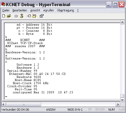
First, the configuration data should be verified. The controller reads these data from its memory directly. Therefore, this test must always work, if it was programmed correctly. The following picture shows the display of the commands "k", "h", "s", "c":
Test the Network connection:
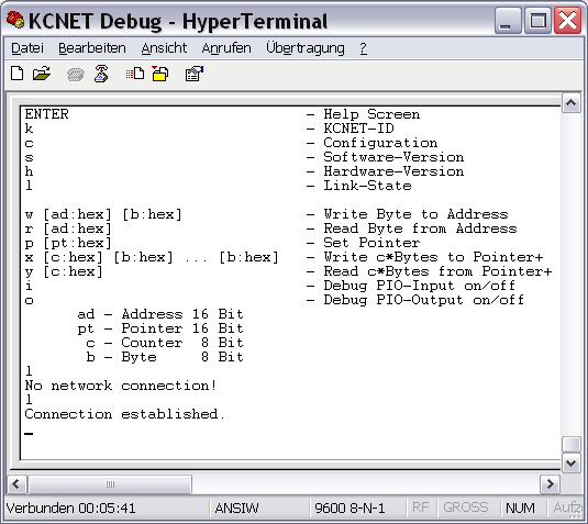
The W5100 reports on a port pin of the controller, whether there is a physical connection to the network or not. That would be the next test, which is carried out with the command "l".
The command "l" notifies with the message "No network connection!", if no network cable is connected with the network module.
If the interface is connected with the network switch or router, the green LED of the network module lights and the command "l" displays the message "Connection established.".
So, you know that the network module is working. If it does not, the error can be caused from the hardware up to the module only, or the network module itself, because the controller works.
Test the TCP/IP-Stack memory-interface:
The next step would be to review whether the RAM interface of the W5100 can be accessed without faults.
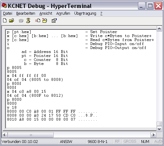
The commands "p", "x" and "y" are used for this purpose. The command "p" tells the debugger the address in the KCNet interface, where it has to read or write the bytes in the commands "x" or "y". After each byte, which has been transferred, the program in the controller increases that address independently by 1. So, you can read or write whole memory blocks of consecutive addresses at once.
You should compare the relevant datasheet section of the W5100 with the commands and their parameters, to understand the test. Here, then, is the significance and impact of the commands, according to the following screenshot:
| p 8005 | - sets the address pointer to 8005H - there is the register SUBR (Subnet Mask Register) - the debugger quits the command with the written address in the following line |
| x 04 ff ff ff 00 | - writes 4 Bytes at once from the current address pointer with increasing address:
8005H=FF- now, the register SUBR contains the Subnetmask 255.255.255.0 - the debugger quits the command with the written addresses |
| p 800f | - sets the address pointer to 800FH - there is the register SIPR (Source IP Address Register) - the debugger quits the command with the written address |
| x 04 c0 a8 00 15 | - writes 4 Bytes at once from the current address pointer with increasing address:
800FH=C0- now the register SIPR contains the IP 192.168.0.21 - the debugger quits the command with the written addresses |
| p 8000 | - sets the address pointer to 8000H - the debugger quits the command with the written address |
| y 18 | - reades back 24 Bytes at once from the current address pointer with increasing address - the debugger sends a HEX/ASCII-dump to the terminal program - every line shows 8 Bytes with address, HEX-Bytes and ASCII-Bytes |
Now, this output is compared with the previously transmitted input at the addresses of the SUBR and SIPR registers. Only when the same content is displayed in the terminal dump was the test successful.
If not, the hardware connection from the controller to the network module is faulty. Then, all lines of the MCU bus interface, as well as the address and data bus, must be checked.
The W5100 works in the network already, if everything is correct. You can PING from other parties in the same network to the entered IP address, and the KCNet interface answers.
Test the TCP/IP-Stack function:
Since the chip is put into service through the writing of memory addresses, one can do a function test in this way. You write a command into a register of the stack, and observe whether it is performed correctly.
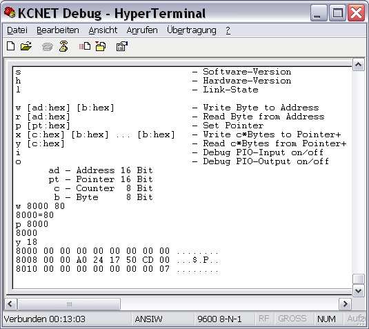
The following steps perform a software reset. Afterwards, all of the above entered parameters must be cleared:
| w 8000 80 | At address 8000H is the MR Register (Mode Register). Setting Bit 7 of this register triggers the software reset. - writes the Byte 80H (10000000B) to address 8000H - the debugger quits the command with the address and the written Byte |
| p 8000 | - sets the address pointer to 8000H - the debugger quits the command with the written address |
| y 18 | - reads back 24 Bytes at once from the current address pointer with increasing address - the debugger sends a HEX/ASCII-dump to the terminal program - every line shows 8 Bytes with address, HEX-Bytes and ASCII-Bytes |
The TCP/IP-stack is back in the state, such as after power on. All registers have been reset and are loaded with their default values. Even the Bit 7 of MR is then cleared automatically.
As you can see, the inputs are gone, all the registers were set to the default value 0. The PING to the previously given IP address is no longer answered.
Test the Z80-PIO communication:
Finally, we come to the last test. Now, the KCNet interface must be connected to the Z80-System, because we want to check the link between the Z80 bus and the MCU system. Start the interface test program CPMNET.COM at the Z80 system, and go to the interface menu. There are some functions which send appropriate test commands of the KCNet protocol to the MCU system.
Use the commands "i" and "o" of the debugger in order to activate the realtime display of data traffic to and from the Z80-PIO. Next, send test commands to the interface with the help of CPMNET.COM. All data sent from the Z80-PIO to the controller, and sent back from the controller to the Z80-PIO, will appear in the window of the terminal program simultaneously.
The following picture was taken, however, with the program CAOSNET.KCC on a KC85 system. The CP/M program sends additional sequences to the interface between calling menu commands, which hangs together with the menu management of CPMNET.COM. Therefore, the displayed data are the same under CP/M in principle, but don't agree fully with the screenshot.
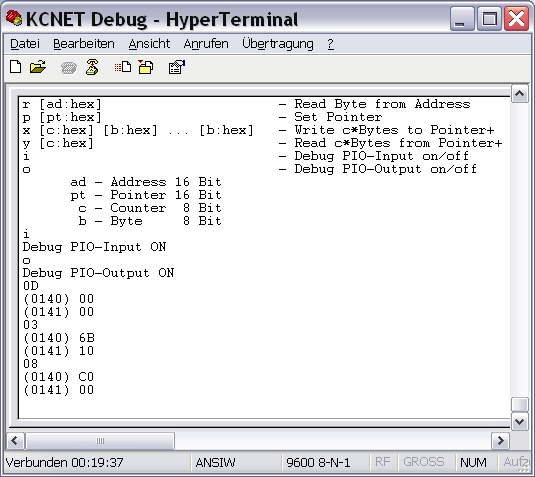
The screenshot shows the following commands of the KCNet protocol with their answers from the interface:
| Command | # DEC | # HEX | Answer | Value |
| Read Command Errors | 13 | 0D | 0000 | 0 Errors |
| Read Timer | 3 | 03 | 106B | 4203 ms |
| Read Dynamic Port Number | 8 | 08 | C000 | Port 49152 |
If nothing happens or there is something wrong, the failure lies in the hardware of the Z80-PIO, the Z80 bus logic, or in the interface connections from the Z80 system up to the controller.
All bracketed numbers are address information, which not belong to the protocol. These extra information is added from the debugger in realtime, so the answers are more understandable and more readable. If a question mark is displayed, the controller has not understood the PIO command. Such a sequence causes a command error in using the KCNet Protocol!
Please switch off the PIO protocol functions, if you don't need them! Both functions restrict the transmission speed to 9600 baud, this greatly slows down the PIO communication, too!
The sent addresses from the terminal program are not checked : you have full access to the entire RAM of the controller. One should, therefore, not write to the addresses from 0 to 500H because, otherwise, the firmware can crash!
Those, who arrive at this point successfully, have achieved the goal : the interface should work in the Z80 system!
As already explained, you can also execute the last test with the Z80 software immediately. If everything is running, then it's okay. But if nothing happens, you should do, step by step, the specified tests in order to isolate the cause of the malfunction.
Another important point right at the end : if the diagnostic interface is not used currently, there nothing should be connected! Once a character is sent from the outside to the controller, it stops everything else and is waiting for the end of the reception, which is the ENTER key code. If it does not come, the PIO interface is blocked!
For example, Linux systems send bytes to the COM port during the boot sequence and thus block the Z80-PIO communication. Looked from the perspective of the Z80 system, the interface behaves like defect!
